ROS Arduino Serial

Please refer to this tutorial of the ultrasound sensor HC-SR04.

Ultrasound sensors measures distance by sending sound waves against objects in front of it and receiving the echos (so it doesn’t work well against objects that absorb sound, e.g. furs).

This code runs in the Arduino, and communicates the message serially through the USB cable to the roscore on the laptop.

#define trigPin 12
#define echoPin 13

// 12 and 13 refers to the pin numbers on Arduino
// You can choose to use any pins on the Arduino for digital 
// signal read and write (which sensor uses) 

#include <ros.h>
#include <std_msgs/Int16.h>

ros::NodeHandle nh;

std_msgs::Int16 int_msg;
ros::Publisher arduino("distance", &int_msg);

// Standard ROS node intialization

void setup() { // Setup code runs only once
  //Serial.begin (9600);  
  // You can choose to see output on a serial monitor
  // on the computer 
  // But from what I found, Arduino can't seem to maintain
  // both serial communication to ROS and serial monitor
  pinMode(trigPin, OUTPUT); // marking pins to be read and write 
  pinMode(echoPin, INPUT); 
  nh.initNode();
  nh.advertise(arduino); 
}
void loop() { // This part of the code runs repeatedly
  long duration;
  int distance;

  digitalWrite(trigPin, LOW); // This is just setup code 
  delayMicroseconds(2);       // So that ultrasound sensor would
  digitalWrite(trigPin, HIGH);// start reading
  delayMicroseconds(10);
  digitalWrite(trigPin, LOW); 

  duration = pulseIn(echoPin, HIGH); 
  // The data coming in from ultrasound sensor is just 
  // digital data (0, 1), but it signifies distance data 
  // (0 ~ 200) by sending "pulses" of certain length 

  distance = (duration/2) / 29.1;
  int_msg.data = distance;

  if (distance >= 2000 ) {
    //Serial.println("Out of range");
  }
  else {
    //Serial.print(distance);
    //Serial.println(" cm");
    arduino.publish(&int_msg);
    nh.spinOnce();
    // Standard publish routine for ROS
  }
  delay(500); // Wait 500 ms before running again
}
~


ROS and Serial Communication

Recommended reading: Serial Communication, ROS Serial – Arduino tutorial, Arduino Basics

Beneath all the software abstractions, much of the communications between the devices we use daily are electrical signals, in either analog or serial form.

Analog communication utilizes all range of the voltage allotted by the medium (e.g. 0v – 5v for Arduino). The range is used to deliver a granular form of data; for example, an analog temperature sensor might indicate a low temperature with a low voltage and high temperature with high voltage. While an analog input might simplify processing of the communication (just pass the voltage levels through an equation), it is also error-prone in many of the cases due to the possibility of electrical noises.

Serial/digital communication is a form of communication that essentially utilizes bits to communicate – sending 2 kinds of voltages, no voltage indicating a low, or off, signal and some high voltage indicating an on signal. While the serial communication prevents much of the noise (by using two range of disparate volts), the devices that send and receive the communication would need some sort of a processor to process and retrieve the data that has been abstracted away.

Also, by its encoded nature, serial communication can also reduce miscommunication by using encoding schemes that guarantee that the both parties are communicating properly.

Given that the web pages above present a much better explanation of how analog and serial communications work, I’ll stop my post here. Please contact me if you need any topics clarified.

Setting up ROS client over network

Client code

#!/usr/bin/env python

from service_tutorial.srv import *
import rospy
import sys

def concat_things_client(string1, string2, num1, num2):
 rospy.wait_for_service('concat_things')
 try:
   concat_things = rospy.ServiceProxy('concat_things',   ConcatThings)
   resp = concat_things(string1, string2, num1, num2)
   return resp.result
 except rospy.ServiceException, e:
   print "Service call failed: %s" % e

if __name__ == "__main__":
 if len(sys.argv) == 5:
   string1 = sys.argv[1]
   string2 = sys.argv[2]
   num1 = int(sys.argv[3])
   num2 = int(sys.argv[4])
 else:
   print "Please provide all args"
   sys.exit(1)
   print "Requesting service"
   print "%s" % concat_things_client(string1, string2, num1, num2)

/etc/hosts on the client

127.0.0.1 localhost comp1
127.0.1.1 guest
10.99.0.12 server

# The following lines are desirable for IPv6 capable hosts
::1 localhost ip6-localhost ip6-loopback
ff02::1 ip6-allnodes
ff02::2 ip6-allrouters

127.0.0.1 vultr.guest
::1 vultr.guest

/etc/hosts on the server

127.0.0.1 localhost server
127.0.1.1 guest
10.99.0.10 comp1
10.99.0.11 comp2

# The following lines are desirable for IPv6 capable hosts
::1 localhost ip6-localhost ip6-loopback
ff02::1 ip6-allnodes
ff02::2 ip6-allrouters
#!/usr/bin/env python

from service_tutorial.srv import *
import rospy
import sys

Commands to debug

Are all the network ports necessary to communicate open?

On server – netcat -l 1234 : echo all things received from port 1234

On client – netcat server 1234 : send input to server through port 1234

Can I connect to ROS core through network?

Try running ROS commands, like rostopic

Am I even connected to the server?

ping server

Is the service available?

rossrv list

Is my environmental variables set to what I think they should be?

echo $ROS_MASTER_URI or ${Environmental variable name}

What is my IP?

ifconfig and check under wlan0 and wlan1.

Modifying Sensor Data with ROS


Here is a sample code that modifies sensor data with ROS:

import rospy
from sensor_msgs.msg import Imu

def imu_callback(msg, pub):
 msg.linear_acceleration.z += 9.3
 pub.publish(msg)

def main():
 rospy.init_node('imu_without_g')
 pub = rospy.Publisher('imu_without_g', Imu, queue_size=10)
 rospy.Subscriber('imu/data', Imu, imu_callback,callback_args=pub) 
 rospy.spin()

if __name__ == '__main__':
 main()
def imu_callback(msg, pub):
 msg.linear_acceleration.z += 9.3
 pub.publish(msg)

The callback is whenever Imu msg arrive, with an additional argument of pub (which is specified in the rospy.Subscriber call). I can modify the msg using the dot notation (with names you can find out with command rosmsg show sensor_msgs/Imu).

def main():
 rospy.init_node('imu_without_g')
 pub = rospy.Publisher('imu_without_g', Imu, queue_size=10)
 rospy.Subscriber('imu/data', Imu, imu_callback,callback_args=pub) 
 rospy.spin()

I initialize a publisher to publish modified IMU data. Since this modified data will be published onto a different topic, you’ll have to redirect the topic of the imu for each nodes that use IMU data in the future.


ROS and Sensors

Recommended reading: ROS Sensor msgs, RViz (wiki.ros.org/rviz), Camera on ROS

One of the main goals ROS had set out to achieve was to remove redundant and unnecessary work in robotics. By providing sensible interfaces (ROS messages) and tools that utilize the interfaces, ROS removes lots of unnecessary work that would have been required with sensors.

Please refer to the camera section of ROS.

Observe that the sections are divided into multiple parts. First, there are software and tools that complement or enhance the sensing capabilities of the camera. These packages are generally, if not all, device-independent – that is, they function from the inputs of messages (topics).

Then, there are hardware drivers specific to each camera, or more generally, types of camera. These packages are either written by the manufacturers themselves or other programmers who wanted to connect the devices to ROS. These packages take raw data from the sensors and publishes it to ROS topics, or allows the sensors to be configured using ROS API (services or something called dynamic parameters).

Since the software tools and hardware drivers communicate through the common ROS interface, you can choose to only change one of them if there is an issue. For example, you can swap the cameras and hardware drivers, but still use the same software package for the large part, or vice versa.

Another thing to note is that devices are listed by the connection type (USB, Serial, Ethernet), as the devices also go through the common Linux interfaces for each types as well, generally through the ports (not the network ports discussed below).

The ports (with names like /dev/ttyUSB0) allows the users on Linux to read and write from the devices. Some notable characteristics of the ports are that they are …

  • allocated dynamically unless specified otherwise (the first USB device is allocated under /dev/ttyUSB0, the second USB device /dev/ttyUSB1, …)
  • Are treated as a file in Linux (which means that all the things that come with files are with ports, like read and write permissions)

Generally, the issue of reading and writing data off these ports will be abstracted away by the drivers (by their purpose).

However, in the cases in which drivers are not provided, the read and write would have to be performed in a specific fashion. For example, the port names specified above indicate (/dev/”tty”) that they are serial ports, which means that you have to communicate them with a specific baud rate (rate of communication), stop bit (signifying end of message), and delimiter (character that indicates the end of message).

For more information on serial port, skim through https://en.wikipedia.org/wiki/Serial_port.

However, as I stated before, we can skip over these complexities and deal with the abstractions of ROS instead.

Please refer to: http://docs.ros.org/api/sensor_msgs/html/msg/Image.html

Like with all ROS messages we have dealt with before, we can do likewise with the ROS image messages. We can assess the header (which contains timestamp, which is necessary to sync up all the sensor data together), put in image data as arrays of ints, and specify the encoding as a string (encoding schemes specify how the row of ints should be read to produce an image).

Other ROS interfaces, as mentioned before, are services (which we can write clients for) and parameters (which can easily be specified when launching the node).

Utilizing ROS interfaces are as simple as they sound – in the package usb_cam (http://wiki.ros.org/usb_cam), you can get images from topic ~<camera_name>/image, set parameters by alongside rosrun like “image_width:=500”, and request that ROS node do somethings by writing clients as specified by the srv files.


Networking for Linux and ROS – Week 7

Recommended material: SSH essentials, ROS on multiple machines, ROS Network Setup , Turtlebot setup

Robots generally require lots of networking, due to the constraints of portability, limited computational power, and robot’s usual multi-part composition. This unfortunately meant that programmers were often required to deal with the fun, easy networking problems of networking.

Thankfully, ROS, with its approach of treating everything as a node and its publisher-subscriber model, removes much of the difficulty that comes with networking – in fact, there is hardly a difference between the node on the computer and the node elsewhere in the network.

As with anything in life, there are some caveats. One, you still have to deal with the underlying networking for Linux/OSes. Second, you do need to setup the environment so that everything may recognize one another.

First, please refer to the ROS on multiple machines tutorial, referenced above. Below are basic information/definition about networking below.

I.P. Address (Internet protocol address) – the number that is used for the network devices (routers, internet service providers) to identify you. There are several different IPs – there is one specific to your machine, generated by your machine (127.0.0.1), the local address generated by the router (or school network in our case, and the address used over the internet (e.g. the address I provided for the virtual Linux instance).

DNS (Domain Name Resolution) – a server that translates an IP address to a rememberable name (google.com); if you look at the ROS network setup, there is a local alternative to this by changing the configuration file.

Static/Dynamic address – Once declared static, IP addresses are each dedicated to a machine, not changing once it comes on and off. For dynamic addressing, each machine in the network is given an available address when they log in to the network, using method called DHCP. Typically, most large networks and routers do dynamic addressing, and static address is used generally for small, private networks or tools that require constant address (e.g. websites).

Port – Necessary appendage to IP addresses for there to be a connection; it generally indicates the type of the connection – 80 is used for HTTP, 25 for SMTP (email), and 22 for SSH. Beyond these commonly used ports, you can use the ports for your own communications. Network admins or routers with strict security policy tend to block all the ports that are not used, as restricting ports restricts malicious people accessing the network in via brute force.

Firewall –As mentioned above, routers can block ports and specific IP addresses from being used for outside communications. Some ways to get around this is to use something called VPN (Virtual Private Network) and pass that data you were share through one port through a port already open (Port 80 of HTTP generally).

MAC Address – Hardware-specific (to network card) addresses used for – you guessed it – hardware identification. Note that MAC addresses are only known to each once they are connected; you can’t connect to another computer using MAC Address.

Now, back to the page. To summarize the page, let me emphasize that once you set up the ROS_MASTER_URI environmental variable (variables that are stored and used in the shell like bash) and the connections, the ROS nodes on separate computers can communicate immediately using ROS methods like topics and services.

Once those things are done, you should be set – that is, of course, if you were able to setup everything without trouble.

If you are indeed in trouble, refer to the tools below to troubleshoot the issue.

ssh – as always, you could use it to access the other computer through a network. You can also scp to copy files through ssh.

ifconfig – reveals network information, like MAC address, device name (wlan0, etc), and IP address

ping – checks if the computer is connected to a specific IP address. To test connection to local computers, use ping <local_address>. To test internet connection, use ping 8.8.8.8 – which is one of the Google’s addresses. You can also verify things like network latency, if there is any network “packets” being dropped (not getting response).

tracert – Use it to check what devices are between your network connection.

Router address – The router configurations are accessible by typing its address into a browser, and are generally addresses with two one’s at the end of the addresses of the computer (i.e. 192.168.1.103 computer address generally translates to 192.168.1.1 for routers).

nmap / ping broadcasting – To find the IP address of the devices of same network, broadcasting a message in the network and waiting for a response is one of the ways to find it.


Making maps and plans in ROS – Week 6

Recommended material: Udacity AI for Robotics planning lectures, in particular, lectures on Dijkstra’s and A*

In detail: ROS maps doc, ROS local planning doc, ROS global planning doc,

As stated in the previous post, all intelligent robots need a way of modeling the world around it in such a way that the model enables for planned action.

Since we are generally interested in mobile robots, we are led to ask – how can the robot map and model the world around it?

In ROS, the map is a 2D discrete costmap – that is, the map is composed of essentially 2D arrays (so the map is discontinuous to certain extent as the pixels on screens are), of each elements containing the “cost” involved to move the robot to the position of the map.

While the ROS documentation details how exactly the cost can be calculated, the cost largely indicates whether the part of the map is unexplored, blocked off due to an obstacle, or open and available to travel.

As you would guess, the cost is informed by the sensor data (e.g. LIDAR indicating whether the obstacles are located), odometry, and robot localization (how the robot is situated relative within the map).

With the costmap that is generated and updated with new sensor data, the typically utilized strategy for planning out robot movement is to divide the planning into two parts – local planning and global planning. Local planning details how exactly the robot will have to move according to the costmap (and the obstacles listed), while the global planning indicates what general direction the robot should move. This general direction informs the local planning by being involved with the score used for the local planning – closer a particular local plan is to the global plan, more it is incentivized to choose that plan.

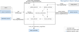
In ROS, the local planning only generates the local plan and does not generate the specific motor commands required to actually move the robot by that plan. Instead, local planning node generates the plan, move_base node takes the plan and generates the cmd_vel based on that plan, and a motor controller node (specific to each motor controller and usually written by the robot team) takes the cmd_vel and generates specific motor commands to move the robot in such a way.

This is generally the approach that ROS will take with all hardware. ROS will provide the logic and the abstraction of how the hardware should behave, and the users of ROS will generally have to provide the code that will interface the software and the hardware together.

To go back to the local planning, the details and the steps of it is on the local planning ROS documentation.

Global planning is even more simple – given a current point and point of destination, ROS will generate a global plan using algorithms that will generate the shortest path between the two, an approach simplified as the map is 2D array.

The simplest approach is Dijkstra’s algorithm, which is an algorithm simply calculates the shortest path by checking the distance of all the points beyond the current point.

Another approach is A*, which can be said to be Dijkstra’s algorithm with a heuristic (rule of thumb) attached to it. A* reduces the amount of the distances that needs to be calculated by only calculating points that are likely to lead to shorter path.

Of course, there are many other shortest path algorithms, each with different strengths, but A* and Dijkstra’s algorithm, perhaps due to their simplicity and general effectiveness, is the one supported by the ROS global planner by default.

So, what exactly is the robot doing when it is navigating? It takes the following steps:

  1. Get a command to go to a particular spot.
  2. Obtain odometry, sensor data, and robot’s position to model how the robot is situated locally.
  3. Based on the global plan, choose a local plan that would best follow it while accounting for the obstacles nearby.
  4. Generate cmd_vel from local plan using move_base node, and generate motor commands using motor controller node
  5. The robot moves
  6. Based on the new sensor/map data, update the global plan (obstacle in the global plan should be accomodated).
  7. Repeat until the point is reached.

Basic Odometry and Localization

Recommended reading: ROS transform tutorials, ROS odometry tutorial, and ROS IMU documentation, ROS GPS documentation

One of the essential information that the robot must generate is its odometry – how the robot changed its position over time.

Two of the simplest ways to generate odometry is to use IMU (inertial measurement unit) and the GPS.

IMU’s measure accelerations of 6 degree – 3 linear accelerations (x,y,z) and 3 rotational acceleration (roll, pitch, yaw), using accelerometer, gyroscopes, and sometimes magnetometers (which calculates the acceleration based on its interactions with Earth’s magnetic field).

One of the drawbacks of IMU is that of most of the sensors – if you solely use IMU for the odometry, the odometry will be off more and more so as the time goes by and errors from the sensors accumulate.

One way to prevent excessive accumulation of misreadings is to “calibrate” the readings against the data from other sensors, in particular,  that of sensors that can get independent reading each time (e.g. GPS/Compass).

The magnetometers serve the same role as the accelerometers and gyroscopes, but its addition serves as a calibrator for the readings from other two sensors. However, its use also means that one needs to make sure that the IMU’s are not next to any other significant magnetic field other than that of earth, such as that of which can be generated by power-hungry electronics.

See this Wikipedia page on IMU: https://en.wikipedia.org/wiki/Inertial_measurement_unit

GPS provides the device with the global position, and is often used as the ultimate calibration data against all the sensors. And with the GPS position data over time, it can likewise be used to generate odometry.

However, due to the nature of GPS, solely using GPS for odometry is not recommended. For one, since GPS receives data from the satellites, the position data is received with a long latency compared to other sensors, leading to inaccurate odometry. Also, GPS require open space to be able to communicate to the satellites and fails to get any data if space is not provided. Lastly, most GPS are not accurate and could have error upto 1 meter or more.

Despite these problems of each sensors, IMU and GPS can be used well together to generate decent odometry – see Uber/Google Maps.

However, in order to do so, two things must happen. GPS and IMU data must be combined

GPS and IMU data must be combined together appropriate to form one, more accurate odometry data. This is done in ROS with a package called robot_pose_ekf, which uses something called efficient Kalman filter to combine multiple sensor data together.

Second, GPS and IMU’s data needs to be provided relative to the robot, not the sensors. While this may not be necessary when the robot and the sensors are small enough and situated “correctly” to each other (sensor is not too far from robot, etc), this will become an issue as the robot gets larger and sensors more distant from each other.

This problem is solved using the tf package in ROS, which provides the transformation between the sensors and the robot. In tf package, robot is often labeled to be the “base_link” with which all the sensors are located relative to it – as specified by the transformation, or the specified distance between the robot and the sensor. Without that transform information, the combination of the odometry data will not be accurate, as sensors could provide different information based on their location relative to the robot.

So, to specify explicitly, this is what needs to be done:

  1. Get the sensor data from the IMU and the GPS.
  2. Transform both IMU and GPS relative to the robot.
  3. Combine IMU and the GPS data using EKF.

Questions and Answers of Robotics in ROS – Week 4

Recommended readings/lectures: ROS wiki on Navigation stack, Udacity’s Artificial Intelligence for Robotics (brief discussions of Unit 1, 4), AI page for Wikipedia on paradigms and approaches, ROS Wiki on data types

One of the things that got me involved in robotics was the fact that a good robot have to be a sufficiently intelligent agent – capable of sensing the “right” parts of the environment (computational cost involved in sensing requires that every agent be discerning) and acting real-time based on those decisions.

Thus, the challenges of robotics involve those two questions – how and what should the robot sense in the environment, and how can the robot act based on that data in a way that could mimic the future-planning and strategic agents like us?

First, let us address the first question – what exactly is involved in the robot’s perception of the environment, or phrased more concretely, why is making a perceptive robot difficult?

One cause of difficulty is the inherent uncertainty that comes with perception. Whether it is caused by the environment or the sensors, the uncertainty of perception necessitates that the robots process what they perceive, and discern the probable reality based on their previous perceptions. For example, we humans can discern that the visual illusions are illusions by analyzing the senses and declaring them to be false, based on our limited understanding of our visual system.

The idea of taking bunch of uncertain things to unify them into a more certain conclusion is an essential idea of robotic perception, and it inherently involves probabilities.

Similarly, another cause of difficulty is the difficulty of integrating multiple sensory data to form one (sometimes multiple) coherent model. Effective perceiving agents have multiple kinds of senses. For example, humans have senses of vision, tactile, etc – many of which informing another sense (e.g. food tastes better if you can smell them). Likewise, robots have a wide array of disparate sensors – ranging from LIDAR (distance sensor that uses laser), infrared sensor, wheel encoders (keeps track of wheel rotations) – and they must be able to utilize all of them to deliberate an action (not necessarily a cohesive action, some theory of AI/robotics argue for the possibility of separate sensors and actuators (limbs of robots) within one robot – an arm acting separately from the body, for instance).

Not only can the type of sensor data be different, but the sensory data could be coming from different parts of the robot – a camera on the left arm and a right arm, for instance. Such scenario gives way to its own sets of problems: how do we “sync” up the changes between the two cameras to get the one coherent view of the room? What does the camera on the arms inform us of the situation the robot is in (the body, etc)?

After the issue of the senses and perception, we are then confronted with the issue of acting and planning (for the future). Indeed, any robots worth their money must be able to plan for the future in some way – not only for the effectiveness of the action, but for the intelligence of the robot.

First question we can think of is the issue of producing good models of reality based on the perceptions. Yes, the perception and sensor data may be in, but they are of no use to us (and the robot) if they can’t be modeled and “understood” properly. For example, if the LIDAR returns to us a 2D vector of points as perceived relative to the sensor, how or for what can we use the data?

Another question is a practical one of making real-time decisions based on the model. Even if the robot have the best model in the world, yet if there is no computationally practical way of acting real-time according to the model, then the robot would be terrible and the model useless. While this practical concern had been well mitigated by the Moore’s Law, it is still and will be a concern in the future.


These issues are thankfully addressed to some extent in the ROS library, particular in the part of the library called the navigation stack. Navigation “stack” features many nodes that each deal with an issue.

The navigation stack largely addresses these issues in the context of mobile, autonomous robots. As seen in the diagram below, nodes that deal with sensor data and perception goes into the box part of the diagram, which largely acts as a brain (more specifically, a state machine) that gives out a command for action (cmd_vel and path for the future). With that cmd_vel, the programmers would tell the robot how to move, writing a motor controller program that can receive the commands in terms of cmd_vel.

In the upcoming days, the nodes you’ll interact with will be nodes that will serve to be basic processor for the sensors – taking in perception and providing the data in a specific format.

overview_tf

Callbacks and Synchronicity – Week 3

Robotics and its software differ from a typical software in its two main requirements.

The first requirement is that robot software must react differently based on environmental changes and conditions – often modeled by a state machine and its states (see here, but at its simplest, it’s just if’s in a while loop).

For example, should the robot not enter into a recovery state after ramming into some obstacle, rather than continuing to pummel through? Even if all the visuals and sensor data may be the same, the robot must act differently in a recovery state than the normal state.

Another requirement is that the robot (the state machine above or something else) needs to be able to handle inputs and requests from multiple sources – from the sensor data, requested actions, and such. Here, the complexity emerges, and ROS is handed the duties of a typical operating system – managing multiple programs at once.

ROS, in its distributed approach, does not have THE state machine, but rather leaves it to each node to determine its own state and resolve the potential conflicts (an approach supported by recent neuroscience advances).

So, when designing nodes for ROS, one must be aware of these requirements.

But first of all, let us first discuss the service tool, which is a synchronous way to establish one-to-one communication, which means that there is an order to the communications. The order is the following: A node (client) would send a request to another node (server), possibly waiting for a reply as the server processes the request.

Where in the code do the waiting and processing happen? The waiting happens at spin() and spinOnce(), while the processing happens in the callback.

Each node, when they receive messages through topics or service, does not immediately process them, as they very well might be doing something more important. Instead, the messages are held in the queue (a line essentially) and processed as a batch during the spin() commands.

So what is the difference between spinOnce() and spin()spin() is essentially spinOnce() called in a loop – once the node runs spin(), the node will now only deal with the callbacks. By comparison, spinOnce() allows the node to process the callbacks at the designated time “once”.

So when should you use each? You should use spinOnce() if you have a code not part of the callback that constantly needs to run and spin() if the server only needs to deal with callbacks from then on. Also, with spinOnce(), you need to be aware of the time that will take to process the tasks between spinOnce(), making sure that the tasks will not prevent callback from activating too late.

And for the services in general, you need to also consider the time that the service will take, making sure it doesn’t occupy the server for too long. Otherwise, the server will not be able to react quickly to the inputs from other nodes – perhaps a command that is requesting for the robot to freeze immediately. Thus, it is generally recommended that services be simple, short requests.

However, you would need the ability to command a robot to do a more complicated task – or even allow for multitasking of tasks. For those requirements, there is the action lib. In contrast to service, it is – and must be – an asynchronous way to communicate one-to-one. 

Why the must? The actions must be asynchronous, as for actions with a long-time frame (~seconds), the state of the robot might change, with actions needed to be interrupted and continued later. So actions are asynchronous because the execution of action is not fixed – unlike services, which can’t be interrupted.

While the exact details of both service and action is in the respective tutorials, these differing goals for services and actions must be accounted for when making servers (nodes) for each of them – asking if the service or action would be more appropriate at this point.

Assignment: Implement a client/service, in which client sends in a service to the server to change the state of the server in some way.