Making maps and plans in ROS – Week 6

Recommended material: Udacity AI for Robotics planning lectures, in particular, lectures on Dijkstra’s and A*

In detail: ROS maps doc, ROS local planning doc, ROS global planning doc,

As stated in the previous post, all intelligent robots need a way of modeling the world around it in such a way that the model enables for planned action.

Since we are generally interested in mobile robots, we are led to ask – how can the robot map and model the world around it?

In ROS, the map is a 2D discrete costmap – that is, the map is composed of essentially 2D arrays (so the map is discontinuous to certain extent as the pixels on screens are), of each elements containing the “cost” involved to move the robot to the position of the map.

While the ROS documentation details how exactly the cost can be calculated, the cost largely indicates whether the part of the map is unexplored, blocked off due to an obstacle, or open and available to travel.

As you would guess, the cost is informed by the sensor data (e.g. LIDAR indicating whether the obstacles are located), odometry, and robot localization (how the robot is situated relative within the map).

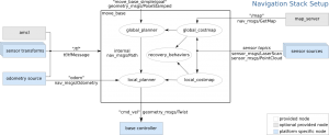
With the costmap that is generated and updated with new sensor data, the typically utilized strategy for planning out robot movement is to divide the planning into two parts – local planning and global planning. Local planning details how exactly the robot will have to move according to the costmap (and the obstacles listed), while the global planning indicates what general direction the robot should move. This general direction informs the local planning by being involved with the score used for the local planning – closer a particular local plan is to the global plan, more it is incentivized to choose that plan.

In ROS, the local planning only generates the local plan and does not generate the specific motor commands required to actually move the robot by that plan. Instead, local planning node generates the plan, move_base node takes the plan and generates the cmd_vel based on that plan, and a motor controller node (specific to each motor controller and usually written by the robot team) takes the cmd_vel and generates specific motor commands to move the robot in such a way.

This is generally the approach that ROS will take with all hardware. ROS will provide the logic and the abstraction of how the hardware should behave, and the users of ROS will generally have to provide the code that will interface the software and the hardware together.

To go back to the local planning, the details and the steps of it is on the local planning ROS documentation.

Global planning is even more simple – given a current point and point of destination, ROS will generate a global plan using algorithms that will generate the shortest path between the two, an approach simplified as the map is 2D array.

The simplest approach is Dijkstra’s algorithm, which is an algorithm simply calculates the shortest path by checking the distance of all the points beyond the current point.

Another approach is A*, which can be said to be Dijkstra’s algorithm with a heuristic (rule of thumb) attached to it. A* reduces the amount of the distances that needs to be calculated by only calculating points that are likely to lead to shorter path.

Of course, there are many other shortest path algorithms, each with different strengths, but A* and Dijkstra’s algorithm, perhaps due to their simplicity and general effectiveness, is the one supported by the ROS global planner by default.

So, what exactly is the robot doing when it is navigating? It takes the following steps:

  1. Get a command to go to a particular spot.
  2. Obtain odometry, sensor data, and robot’s position to model how the robot is situated locally.
  3. Based on the global plan, choose a local plan that would best follow it while accounting for the obstacles nearby.
  4. Generate cmd_vel from local plan using move_base node, and generate motor commands using motor controller node
  5. The robot moves
  6. Based on the new sensor/map data, update the global plan (obstacle in the global plan should be accomodated).
  7. Repeat until the point is reached.

Basic Odometry and Localization

Recommended reading: ROS transform tutorials, ROS odometry tutorial, and ROS IMU documentation, ROS GPS documentation

One of the essential information that the robot must generate is its odometry – how the robot changed its position over time.

Two of the simplest ways to generate odometry is to use IMU (inertial measurement unit) and the GPS.

IMU’s measure accelerations of 6 degree – 3 linear accelerations (x,y,z) and 3 rotational acceleration (roll, pitch, yaw), using accelerometer, gyroscopes, and sometimes magnetometers (which calculates the acceleration based on its interactions with Earth’s magnetic field).

One of the drawbacks of IMU is that of most of the sensors – if you solely use IMU for the odometry, the odometry will be off more and more so as the time goes by and errors from the sensors accumulate.

One way to prevent excessive accumulation of misreadings is to “calibrate” the readings against the data from other sensors, in particular,  that of sensors that can get independent reading each time (e.g. GPS/Compass).

The magnetometers serve the same role as the accelerometers and gyroscopes, but its addition serves as a calibrator for the readings from other two sensors. However, its use also means that one needs to make sure that the IMU’s are not next to any other significant magnetic field other than that of earth, such as that of which can be generated by power-hungry electronics.

See this Wikipedia page on IMU: https://en.wikipedia.org/wiki/Inertial_measurement_unit

GPS provides the device with the global position, and is often used as the ultimate calibration data against all the sensors. And with the GPS position data over time, it can likewise be used to generate odometry.

However, due to the nature of GPS, solely using GPS for odometry is not recommended. For one, since GPS receives data from the satellites, the position data is received with a long latency compared to other sensors, leading to inaccurate odometry. Also, GPS require open space to be able to communicate to the satellites and fails to get any data if space is not provided. Lastly, most GPS are not accurate and could have error upto 1 meter or more.

Despite these problems of each sensors, IMU and GPS can be used well together to generate decent odometry – see Uber/Google Maps.

However, in order to do so, two things must happen. GPS and IMU data must be combined

GPS and IMU data must be combined together appropriate to form one, more accurate odometry data. This is done in ROS with a package called robot_pose_ekf, which uses something called efficient Kalman filter to combine multiple sensor data together.

Second, GPS and IMU’s data needs to be provided relative to the robot, not the sensors. While this may not be necessary when the robot and the sensors are small enough and situated “correctly” to each other (sensor is not too far from robot, etc), this will become an issue as the robot gets larger and sensors more distant from each other.

This problem is solved using the tf package in ROS, which provides the transformation between the sensors and the robot. In tf package, robot is often labeled to be the “base_link” with which all the sensors are located relative to it – as specified by the transformation, or the specified distance between the robot and the sensor. Without that transform information, the combination of the odometry data will not be accurate, as sensors could provide different information based on their location relative to the robot.

So, to specify explicitly, this is what needs to be done:

  1. Get the sensor data from the IMU and the GPS.
  2. Transform both IMU and GPS relative to the robot.
  3. Combine IMU and the GPS data using EKF.

Questions and Answers of Robotics in ROS – Week 4

Recommended readings/lectures: ROS wiki on Navigation stack, Udacity’s Artificial Intelligence for Robotics (brief discussions of Unit 1, 4), AI page for Wikipedia on paradigms and approaches, ROS Wiki on data types

One of the things that got me involved in robotics was the fact that a good robot have to be a sufficiently intelligent agent – capable of sensing the “right” parts of the environment (computational cost involved in sensing requires that every agent be discerning) and acting real-time based on those decisions.

Thus, the challenges of robotics involve those two questions – how and what should the robot sense in the environment, and how can the robot act based on that data in a way that could mimic the future-planning and strategic agents like us?

First, let us address the first question – what exactly is involved in the robot’s perception of the environment, or phrased more concretely, why is making a perceptive robot difficult?

One cause of difficulty is the inherent uncertainty that comes with perception. Whether it is caused by the environment or the sensors, the uncertainty of perception necessitates that the robots process what they perceive, and discern the probable reality based on their previous perceptions. For example, we humans can discern that the visual illusions are illusions by analyzing the senses and declaring them to be false, based on our limited understanding of our visual system.

The idea of taking bunch of uncertain things to unify them into a more certain conclusion is an essential idea of robotic perception, and it inherently involves probabilities.

Similarly, another cause of difficulty is the difficulty of integrating multiple sensory data to form one (sometimes multiple) coherent model. Effective perceiving agents have multiple kinds of senses. For example, humans have senses of vision, tactile, etc – many of which informing another sense (e.g. food tastes better if you can smell them). Likewise, robots have a wide array of disparate sensors – ranging from LIDAR (distance sensor that uses laser), infrared sensor, wheel encoders (keeps track of wheel rotations) – and they must be able to utilize all of them to deliberate an action (not necessarily a cohesive action, some theory of AI/robotics argue for the possibility of separate sensors and actuators (limbs of robots) within one robot – an arm acting separately from the body, for instance).

Not only can the type of sensor data be different, but the sensory data could be coming from different parts of the robot – a camera on the left arm and a right arm, for instance. Such scenario gives way to its own sets of problems: how do we “sync” up the changes between the two cameras to get the one coherent view of the room? What does the camera on the arms inform us of the situation the robot is in (the body, etc)?

After the issue of the senses and perception, we are then confronted with the issue of acting and planning (for the future). Indeed, any robots worth their money must be able to plan for the future in some way – not only for the effectiveness of the action, but for the intelligence of the robot.

First question we can think of is the issue of producing good models of reality based on the perceptions. Yes, the perception and sensor data may be in, but they are of no use to us (and the robot) if they can’t be modeled and “understood” properly. For example, if the LIDAR returns to us a 2D vector of points as perceived relative to the sensor, how or for what can we use the data?

Another question is a practical one of making real-time decisions based on the model. Even if the robot have the best model in the world, yet if there is no computationally practical way of acting real-time according to the model, then the robot would be terrible and the model useless. While this practical concern had been well mitigated by the Moore’s Law, it is still and will be a concern in the future.


These issues are thankfully addressed to some extent in the ROS library, particular in the part of the library called the navigation stack. Navigation “stack” features many nodes that each deal with an issue.

The navigation stack largely addresses these issues in the context of mobile, autonomous robots. As seen in the diagram below, nodes that deal with sensor data and perception goes into the box part of the diagram, which largely acts as a brain (more specifically, a state machine) that gives out a command for action (cmd_vel and path for the future). With that cmd_vel, the programmers would tell the robot how to move, writing a motor controller program that can receive the commands in terms of cmd_vel.

In the upcoming days, the nodes you’ll interact with will be nodes that will serve to be basic processor for the sensors – taking in perception and providing the data in a specific format.

overview_tf